

The semi-automatic container spreader is a specialized attachment designed to grip and release ISO-standard containers. In accordance with GB/T 3220, container spreaders are categorized into three types based on their twistlock actuation methods: manual, semi-automatic, and power-driven. The semi-automatic spreader utilizes the crane's vertical lifting motion as its power source; a mechanical linkage mechanism drives the twistlocks to automatically engage and disengage, eliminating the need for external hydraulic or electrical systems. This product is specifically designed for 20-foot and 40-foot ISO-standard containers.
The ISO 3874 standard ("Series 1 freight containers - Handling and securing") designates the top-lift semi-automatic spreader as an approved method for container handling, requiring that lifting forces be applied vertically to the apertures of the top corner fittings. This semi-automatic spreader is designed in strict compliance with this standard; the spacing between its twistlocks precisely matches the corner fitting apertures of 20-foot and 40-foot containers, ensuring accurate insertion into the ISO-standard corner fittings for safe lifting operations.
Why choose the semi-automatic container spreader for container handling?
Operating Principle: Purely Mechanical Logic
The core advantage of the semi-automatic spreader lies in its purely mechanical locking and unlocking mechanism, which requires no external power supply or hydraulic lines. Its operating cycle is as follows:
Engagement and Mechanical Interlock: As the spreader is lowered onto the top of the container, the guide pins (sensing pins) at the four corners make contact with the container surface and retract upwards, triggering the mechanical interlock of the twistlock mechanism (thereby releasing the rotational freedom).
Twistlock Rotation (Locking/Unlocking): As the crane continues to lower or hoist the semi-automatic spreader, the vertical movement of the lifting hooks is transmitted via springs and a linkage assembly to a triangular drive plate. The drive plate causes a guide block to slide, forcing the drive linkage connected to the twistlock to rotate ±90°; this motion is then transferred through the rotating arm and handle to rotate the twistlock itself by 90°. Once the long axis of the twistlock head (or shoulder) is misaligned with the long axis of the corner casting opening, the mechanism enters the locked state, preventing it from disengaging from the corner casting.
Floating Twistlocks and Fault Tolerance: The four twistlocks utilize a "floating" suspension design-featuring a spherical bearing surface mated with a concave spherical seat-that allows for a certain range of movement. This semi-automatic container spreader design ensures the twistlocks are subjected only to pure tensile force during lifting and facilitates easier insertion into container corner castings that may have slight deformations or welding misalignments, thereby significantly enhancing operational fault tolerance.
Locking/Unlocking Indication: To ensure operational safety, the movement of the actuating linkage drives an indicator pointer to display the lock pin's status. Additionally, a highly visible indicator plate-finished in a high-visibility color for night-time use-is mounted in a prominent location on the spreader, allowing the operator to easily verify the locking status in low-light conditions.
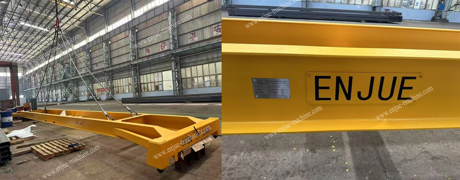
Key Structural and Design Features
Frame Structure
The semi-automatic spreader utilizes a frame-type structure with box-section end beams, ensuring overall torsional strength and stability. Post-welding deformation (bending or warping) is limited to within 1.5% of the center-to-center distance between twistlocks along the length and width, ensuring precise twistlock positioning.
Guide Plate Assembly
The semi-automatic spreader is equipped with passive, fixed, yet detachable guide plates. These plates can move vertically to assist the operator in container alignment while preventing damage from collisions with obstacles. Each spreader features three steel guide plates (minimum thickness: 3 cm; minimum length: 0.9 m) and includes safety measures to prevent them from detaching.

Material and Manufacturing Requirements
Load-bearing structural components: Steel with a yield strength of at least 235 MPa (Q345B) is used, undergoing sandblasting and anti-corrosion treatment before fabrication.
Twistlocks and critical components: Twistlocks are made from high-quality alloy steel (42CrMo) with a yield strength of at least 450 MPa; self-lubricating spherical plain bearings are sourced from renowned domestic brands to ensure wear resistance and reliability.
Welding quality: Butt welds on load-bearing structural components must meet Class I standards (per GB/T 11345) and Class II standards (per GB/T 3323); welds must be free from defects such as cracks, undercut, or slag inclusions.
Semi-automatic Spreader Transfer and Storage
Forklift pockets (150 × 300 mm) are provided to facilitate transfer and handling. Additionally, a storage fixture is included for the lifting wire ropes (φ36 × 8 m, steel core) to prevent damage from crushing or abrasion during transport.


